Carbon capture and storage (CCS) is a way of putting the greenhouse gas CO2 back in the ground after fossil fuels have been burnt. This new technology has the potential to reduce global emissions and allow us to continue using fossil fuels to generate electricity.
-
The rocks under the North Sea in the UK could absorb ca 180 years of CO2 from the country's 20 largest power stations and refineries
-
Scientists monitor CO2 1000 m below the seabed using seismic surveys
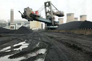
The idea of CCS is simple. Large point sources of CO2, such as power stations, cement factories and refineries, could be connected in clusters to pipelines that would take separated CO2 to wells where it can be injected into former oil or gas fields or salt water soaked pore space in other rock layers (saline aquifiers). The argument is that if the underground storage structure is good enough, the CO2 will stay there for millions of years, just as natural gas does.
Carbon capture
Three styles of CO2 capture are currently favoured in electricity generation.
-
Post-combustion capture separates the CO2 from power station flue gas using chemical solvents.
-
Pre-combustion capture involves converting hydrocarbon fuel (typically methane, or gasified coal) into hydrogen and carbon monoxide (synthesis gas): the CO is reacted with water to form CO2, which is separated from the hydrogen. The latter can be combusted cleanly, while the CO2 is compressed into liquid and transported to a storage site.
-
The oxyfuel method: fossil fuels are burnt in pure oxygen rather than air, resulting in a more complete combustion. The exhaust stream is typically 90 per cent CO2 and 10 per cent water vapour, which can be easily separated from the CO2 by condensation. The captured CO2 is fed directly to pipelines.
Large-scale transport of CO2 through pipes has been operating since the 1970s in the US. In the UK there are plans to operate pipelines on a 'trunk' system at high pressure (about 150 times atmospheric pressure). However, the CO2 might contain some impurities (possibly minor amounts of N2, O2, SOX , NOX and maybe H2 S) and this has implications for the type of steel used in the pipe.
Carbon storage
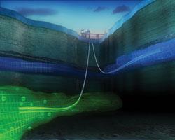
The easiest places to start storing CO2 are depleted gas and oil fields. However, their capacity is quite small - ie only about five billion tonnes of CO2 can be stored in UK depleted gas fields.
Scientists are currently investigating one of the largest, potential storage areas for CO2 in Europe - ie deep beneath the bed of the North Sea. They estimate that the rocks under the UK sector of the North Sea could absorb about 22 billion tonnes of CO2, which equates to 180 years of CO2 from the UK's 20 largest point sources.2
Most of the seabed (about 14 billion tonnes) is made up of porous sedimentary rocks (usually sandstone) at depths greater than 800 m. Sandstone comprises spherical or near spherical minute quartz grains, with the spaces between often filled with saline water at great depth or freshwater at shallow depths. The saline aquifers could provide most of the CO2 storage space but their behaviour and capacity are not well known.
To use this area for CO2 storage we need to understand the effect of displacing water when we pump CO2 into saline aquifers, and we need to know precisely how much safe storage space there is in an aquifer.
Sleipner in the Norwegian sector is the oldest testing site in the world for saline aquifers. A million tonnes of CO2 per year has been injected into the deep Utsira saline aquifer, and more than 11 million tonnes of CO2 is stored here. The CO2 is separated from natural gas produced at the Sleipner East Field below the Utsira (Fig 1).
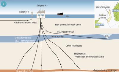
Research shows that we can accurately monitor the movement of CO2 almost 1000 m below the seabed at Sleipner using seismic (earthquake) surveys. The gas is imaged as a sequence of clear reflections within a sandstone aquifer. These reflections come from several layers of CO2 that are stacked above each other throughout the 200 m thick Utsira Formation. Together the layers of CO2 are known as the 'plume' (Fig 2). They are formed as the slightly buoyant CO2 rises through the Utsira sandstone and spreads out beneath several thin shale horizons. By matching past and present seismic data with computer simulations we can model and predict further CO2 movement with some confidence.
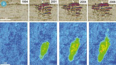
The top layer of the plume can be characterised accurately, and its rate of growth measured. From this the CO2 flowing from the lower parts of the plume to the reservoir top can be estimated. This information can helps us understand how the plume will develop in the long term, over the timescale that the store will need to operate - perhaps hundreds of thousands of years.
Trapping CO2 in the rocks
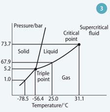
Carbon dioxide can exist in four phases - gas, liquid, solid and a supercritical fluid - in much the same way as water does, but at lower temperatures and pressures (Fig 3). Importantly, it can exist as a relatively dense, stable supercritical phaseat depths of 600-1000 m that are easy to reach with boreholes.
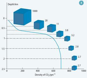
The typical density for stored supercritical CO2 is about 700 kg m-3, so one tonne would occupy only 1.43 m3 compared to approximately 509 m3 at 0°C and 1 atmosphere.
Thus CO2 occupies much less space in the deep subsurface than at the surface (Fig 4).
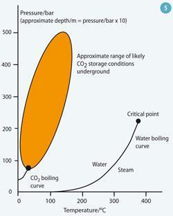
Under the pressure-temperature conditions commonly found in sub-surface storage formations (Fig 5), supercritical CO2 is less dense than, and only slightly miscible with, the water or brine in those formations. It therefore tends to rise under buoyancy until it reaches an impermeable rock, such as shale or salt beds, which traps the gas. This 'physical trapping' of CO2 is the principal means of storing CO2 in geological formations.
Where the distance from the deep injection site to the end of the overlying impermeable formation is hundreds of kilometres, the time for fluid to reach the edge of the deep basin could theoretically be millions of years. In these cases 'hydrodynamic trapping' can occur. As the CO2 moves it can be trapped as small 'bubbles' in pores (known as residual CO2 saturation) or in small, localised structural traps on the base of the sealing formation. Thus slowly migrating CO2 may not actually move very far before becoming effectively immobilised.
Carbon dioxide in the subsurface can also undergo a sequence of geochemical interactions with the rock and formation water that will further increase storage capacity and efficacy. After injection some of the CO2 will dissolve in the local formation water (solubility trapping). Beneficially, once CO2 is dissolved, it no longer exists as a separate phase, thus eliminating the buoyant forces that drive it upwards. Although CO2 is only slightly soluble in water, managing the injection process to optimise mixing between CO2 and water will increase the amount of CO2 stored this way. Dissolution of CO2 in formation waters can be represented by a series of linked chemical equilibria:
CO2(g) + H2O ⇋ CO2(aq) + H2O
H2CO30 ⇋ HCO3-+ H+
⇋ CO32- + 2H+
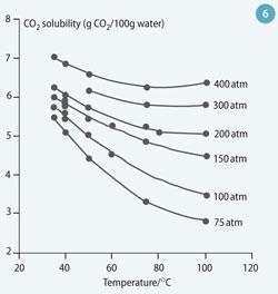
In reality, however, most of the 'solubility trapped' CO2 will be in the form of dissolved CO2 (CO2 (aq)) and bicarbonate ions (HCO3-). The solubility of CO2 in water increases with increasing pressure, but decreases with increasing temperature and salinity.(For the maximum solubility, pure water case see Fig 6.)
Mineralisation
Dissolution is rapid when formation water and CO2 share the same pore space, but once the formation water next to the CO2 is saturated, the rate slows and is controlled by diffusion and convection rates. Carbon dioxide dissolved in water produces a weak acid, which reacts with minerals in the reservoir rock. A wide range of mineral reactions is possible, which can trap CO2 either as bicarbonate ions, or precipitated as secondary carbonate minerals. Relatively fast dissolution (days-months) could occur with carbonate minerals such as calcite or dolomite, which will keep dissolving until they reach equilibrium with the new (ie more acidic) conditions:
CaCO3 + CO2(aq) + H2O
Calcite → Ca2+ + 2HCO3-
CaMg(CO3)2 + 2CO2(aq) + 2H2O
Dolomite → Ca2+ + Mg2+ + 4HCO3-
Silicate minerals react much more slowly (over hundreds to thousands of years), and as well as producing bicarbonate ions can lead to the formation of secondary carbonate minerals if they release enough suitable M2 + ions:
3KAlSi3O8 + 2CO2(aq) + 2H2O Z
K-feldspar
Muscovite (illite) + 6SiO2 + 2 K+ +
Quartz 2HCO3-
CaAl2Si2O8 + CO2(aq) + 2H2O →
Anorthite
CaCO3 + Al2Si2O5(OH)4
Calcite Kaolinite
These are just a few of the many reactions that will occur between CO2 and minerals. Not only are they varied, but they also occur at different rates. We can study them in high-pressure laboratory experiments, through analysis of rocks filled with natural CO2-rich waters, and predictive geochemical computer modelling.
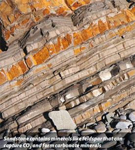
The dissolved CO2 that is converted to stable carbonate minerals ('mineral trapping') is the most permanent form of geological storage. Formation of carbonate minerals occurs from continued reaction of bicarbonate ions with calcium, magnesium and iron from silicate minerals such as clays, micas, chlorites and feldspars present in the rock matrix. Mineral trapping is believed to be comparatively slow, potentially taking thousands of years or longer. Nevertheless, the permanence of mineral storage, combined with the potentially large storage capacity present in some geological settings, makes this a desirable feature of long-term storage.
Scientists estimate3 that for certain reservoirs it will take 5000 years for all the CO2 injected to dissolve or be converted to carbonate minerals within the storage formation. Studies also show that caprocks and overlying rock formations may have an even greater capacity for mineralisation. This is important because even if some CO2 does manage to escape from a reservoir, reaction with overlying rock makes it less likely that it will be released to the atmosphere.
Current issues
A lot of research is being done into CCS but so far no single full chain, full-scale power plant-to-storage project is complete, perhaps because it is expensive, or because it involves contrasting sides of the energy world that are not used to working together.
Despite the difficulties, many scientists see CCS as an important way forward, particularly with the commitment that many emerging nations have to coal-fired electricity. China's growth is astonishing. In one province of China in 2006, for example, 114 million tonnes of CO2 per year were produced from 23 large sources, but by the end of 2007 in the same province, 220 Mt of CO2 was being produced per year from 88 large sources.4 The lowering of CO2 emissions in China (and other rapidly-developing countries) will be vital to the global goal of avoiding a catastrophic temperature rise of 2°C before 2100.

The CCS business could also be a job and wealth creator. UK Government estimates suggest that the CCS business could have a value of £2-4 billion per year by 2030, sustaining between 30 000 and 60 000 jobs in the UK, with a cumulative value of £25-45 billion between 2010 and 2030.5 The UK CCS business will likely take off from regional clusters like the Humber, Teesside, Thames Gateway, the Firth of Forth and Merseyside where existing hydrocarbon and other industrial infrastructure might be used, and offshore engineering expertise can be harnessed. Other European hubs could be Rotterdam, Ruhr and Saar-Rhine.
UK leads the way
The UK is taking a lead in CCS worldwide, both in terms of the Department of Energy and Climate Change's (DECC) Competition to build a full chain demonstration of CCS in the UK, and in the UK's export of knowledge and expertise to big emitters in the developing world (for example China and India). In China the 'UK-China Near Zero Emissions Coal project' (NZEC) plans to demonstrate near zero emissions coal technology through CCS in China and the EU by 2020, and EU and Chinese technologists have been working together to realise this.6 Similarly, India is considering CCS seriously so there might be opportunities here too.
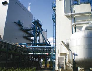
Carbon capture and storage is a new area of science that is moving ahead at a great pace. There will be opportunities for engineers, geologists and chemists and not just in the UK - CCS is likely to be a worldwide industry in the future.
Dr Mike Stephenson is head of energy science and Dr Chris Rochelle is a research geochemist at the British Geological Survey, Keyworth, Nottingham NG125 5GG.
References
- S. Pacala and R. Socolow, Science, 2004, 305, 968.
- S. Holloway, C. Vincent and K. L Kirk, Report no. Coal R308 DTI/Pub URN 06/2027, 2006,.
- E. I. Perkins et al, Proceedings of the 7th International Conference on Greenhouse gas control technologies (GHGT-7) , September 5-9, 2004, Vancouver, Canada.
- Clearer skies for China geoscientist 2008
- DECC consultation
- NZEC website




No comments yet