Use this demonstration to illustrate the greenhouse effect and the role of carbon dioxide as a greenhouse gas
The demonstration includes two parts. In the first, students observe a model of the greenhouse effect in a greenhouse using transparent bottles containing air. In the second, they learn about the role of carbon dioxide by comparing the effects in two separate vessels containing air and carbon dioxide respectively.
The experiments in both parts demonstrate the greenhouse effect by comparing the temperature increases in suitable vessels containing the gases, on exposure to light from a powerful lamp.
Each part of the demonstration will take about 30 minutes. However, the second part can be started well before the first part has been completed if sufficient apparatus is available.
The experiments involve slow, gradual temperature increases. If the temperatures are monitored electronically, with data logging and a live display, the experiment can be allowed to proceed while the class carries on with other work. If ordinary thermometers or electronic thermometers with digital displays are used, the temperatures will have to be recorded at one minute intervals, requiring the attention of the class to time and record for the duration of the demonstrations.
Equipment
Apparatus
For both parts
- Photoflood light bulb, 275 W, in a plain bulb holder (see notes 1 and 2 below)
- Temperature sensors with leads, 3, with data logger and computer display (see note 3)
For part 1
- Plastic drink bottles, transparent, 1 dm3, x2 (see note 4)
- 2-hole bungs, to fit bottles (see note 4)
- Clock, with second hand
- Stand, boss and clamp, x2
For part 2
- Beakers, 250 cm3, x2
- Black card discs, x2
Apparatus notes
- Photoflood bulbs are available from photographic suppliers on the internet, or from photography shops on the high street, at a cost of £10–15 each for a 275 W bulb. The bulb should be fitted in a plain bulb-holder suitably stabilised so that it stands securely on the demonstration bench, and is easily switched on and off by the demonstrator without disturbing the bulb.
- The photoflood bulb should be situated so that the three temperature sensors or thermometers can be placed equidistant from the bulb, as shown in figure 1 below.
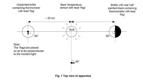
- Check that all three temperature sensors show the same temperature on the computer display when placed in the same temperature environment. Fit two of the sensors through the rubber bungs that will fit into the drinks bottles.
Each of the three temperature sensors should be wrapped with a lead (or prepared aluminium) foil ‘flag’. Each flag is made from a piece of lead foil about 3 x 2 cm such that after wrapping around the sensor, a flag approximately 1 cm wide and 2 cm high made of doubled foil is formed (see figure 2 below).
The sensor should then be positioned so that the face of each flag will be perpendicular to the radiation from the bulb. The end result should be a set of three temperature sensors with flags that are as similar as possible. The sensors carrying their flags need to fit easily through the necks of the drinks bottles.
The setting up of the datalogger and three temperature sensors will depend on the kit available in the school. The handbook for the datalogger will provide the necessary instructions. Suitable software should be used to display the temperature data as a function of time as three lines of different colour on screen(s) visible to the class. Two of the temperature sensors will be required again in part 2, but without the lead flags. - The two drinks bottles for part 1 should be identical, colourless, transparent, PET plastic (recycling code 1) water bottles, fizzy drink bottles or similar, of 1 dm3 capacity, capable of carrying a 2-hole rubber bung in the mouth (see figure 3). One hole is needed to carry the temperature sensor (or the thermometer if used), the other to allow air flow to prevent pressure build-up.
One of the bottles should be painted matt black on one ‘side’ and allowed to dry thoroughly.
The bottles should be secured in an upright position, without obscuring the light path from the lamp.
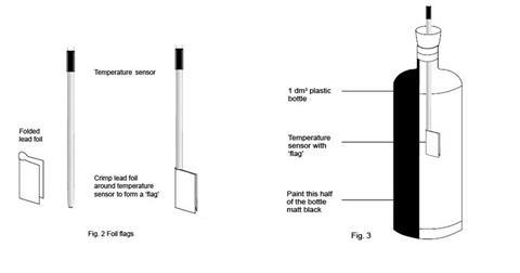
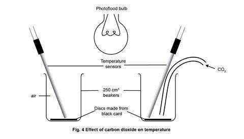
- Finally set up the apparatus for part 1 as in figure 1, clamping as necessary to ensure the arrangement is secure from accidental knocks, and at the appropriate point in the lesson, replace by the simple arrangement for part 2 as in figure 4. Note that the photoflood lamp is now positioned and clamped above the beakers, midway between them.
Chemicals
For part 1
- Lead foil pieces (TOXIC, DANGEROUS FOR THE ENVIRONMENT), about 3 cm x 2 cm, x3 (aluminium foil can be used as an alternative to lead foil but must be either painted black or darkened which happens after it has been in contact with food)
- Matt black paint (for example, blackboard paint)
For part 2
- Source of carbon dioxide gas
- (Optional) One or more of these other gases and volatile liquids:
- Methane (natural gas) (EXTREMELY FLAMMABLE)
- Pentane (EXTREMELY FLAMMABLE, HARMFUL, DANGEROUS FOR THE ENVIRONMENT), 1 cm3
- Hexane (HIGHLY FLAMMABLE, HARMFUL, DANGEROUS FOR THE ENVIRONMENT), 1 cm3
Health, safety and technical notes
- Read our standard health and safety guidance.
- Lead foil, Pb(s), (TOXIC, DANGEROUS FOR THE ENVIRONMENT) – see CLEAPSS Hazcard HC056. In part 1 the lead foil pieces are for making the ‘flags’ around the temperature sensors (Note 3). The Lead foil can be replaced with darkened aluminium foil and the effect is still observed.
- Carbon dioxide, CO2 (g) – see CLEAPSS Hazcard HC020a. For use of a carbon dioxide cylinder also see Laboratory Handbook Section 9.9 about the safe storage and use of gas cylinders. If using solid carbon dioxide (dry ice), this should be obtained within 24 hours of the demonstration in substantially larger quantity than required for the experiment, and stored in a vented insulated container until required. All handling must be done using thermal gloves and handling tongs. If neither a carbon dioxide cylinder nor a supply of dry ice is available, carbon dioxide gas may be generated chemically – see these standard techniques for generating, collecting and testing gases. Replace the thistle funnel shown with a tap funnel or an unstoppered separating funnel. Use about 10 g of small marble chips (calcium carbonate) and about 100 cm3 of hydrochloric acid (2 M) for the carbon dioxide generator. Add the acid a few cm3 at a time to the marble chips to generate a steady stream of carbon dioxide. Either shortly before part 2 of the demonstration, or as part of the demonstration, allow a flow of carbon dioxide to displace the air from the beaker. Alternatively pieces of solid carbon dioxide can be allowed to evaporate in the bottom of the beaker.
- Methane (Natural gas), CH4 (g), (EXTREMELY FLAMMABLE) – see CLEAPSS Hazcard HC045a.
- Pentane, C5 H12 (l), (EXTREMELY FLAMMABLE, HARMFUL, DANGEROUS FOR THE ENVIRONMENT) – see CLEAPSS Hazcard HC045a.
- Hexane, C6 H14 (l), (EXTREMELY FLAMMABLE, HARMFUL, DANGEROUS FOR THE ENVIRONMENT) – see CLEAPSS Hazcard HC045a.
Procedure
Part 1
- With the apparatus set up as in figure 1 above, start the datalogging programme with all three sensors at the same time (which should all show the same temperature), and immediately switch on the photoflood lamp.
- Allow the datalogging to proceed with the graphical display visible to the class. Ensure the class are aware of which graphical trace belongs to which sensor. In about 15 minutes, the three traces should level off, the ‘bare’ sensor showing a typical increase of around 5°C, the clear bottle about 8°C, and the blackened bottle about 13°C.
- If two further temperature sensors and a second datalogger are available, part 2 can be demonstrated while part 1 is running. Alternatively the class can proceed with other tasks until there is a clear result from part 1 on the display screen.
Part 2
- Reset the datalogger and software to start again with inputs from two temperature sensors.
- Start the datalogger and switch on the lamp; the two traces should remain together, though showing a gradual rise.
- When this gradual rise levels off, introduce carbon dioxide as a steady flow into one of the beakers. The trace from that beaker should soon show a higher temperature than the beaker with only air – typically up to 8 degrees higher. If the gas flow is stopped, the carbon dioxide will slowly diffuse out of the beaker, replaced by air, and the temperature should begin to fall again.
- (Optional) Clear the carbon dioxide from its beaker, and repeat 1 and 2 above. Ensure all sources of ignition have been removed. Now introduce a slow stream of methane from the gas tap into the beaker and observe the effect on the temperature trace.
- (Optional) Again repeat 1 and 2 above and ensure all sources of ignition have been removed. Use a dropping pipette to drop about 1 cm3 of the volatile liquid into the beaker. This will slowly evaporate, and the effect on the temperature trace can be followed as it does so.
Teaching notes
In a garden greenhouse, visible light passes through the glass and is absorbed by darker surfaces inside. This absorbed energy heats up the materials, also warming the surrounding air. But convection is restricted by the enclosing glass and the inside temperature of the greenhouse rises. This is the main cause of warming in a garden greenhouse.
However, in addition the warm surfaces re-radiate some of the absorbed energy, but at longer wavelengths in the infrared region of the spectrum. Some of this infra-red radiation is absorbed by glass and contributes to the warming of the greenhouse. It is this latter effect that is called the ‘greenhouse effect’. The greenhouse effect in the Earth’s atmosphere is caused by a number of gases that behave in a similar way to glass. They are transparent to visible light, but absorb in part of the infrared spectrum. Some of these gases are listed in the table. It can be seen that carbon dioxide is the most important greenhouse gas because of its relatively high concentration in the atmosphere rather than its intrinsic greenhouse efficiency.
| Gas | Relative greenhouse efficiency per molecule | Concentration in the atmosphere/ppm | Relative efficiency x concentration/ppm |
|---|---|---|---|
| Carbon dioxide | 1 | 350 | 350 |
| Methane | 30 | 1.7 | 51 |
| Dinitrogen | 160 | 0.31 | 49.6 |
| Ozone | 2,000 | 0.06 | 120 |
| CFC 11 (CCI3F) | 21,000 | 0.00026 | 5.46 |
| CFC 12 (CCI2F2) | 25,000 | 0.00024 | 6 |
In part 1, the experiment demonstrates the situation in a greenhouse using a plastic bottle. It also shows the effect of a black surface absorbing the energy from visible light.
In part 2, however, replacing the plastic bottles with open beakers removes the restriction on convection. The difference in temperature rise between the two beakers comes mainly from absorption by the gases of the radiant (infra-red) energy from the lead discs at the bottom of the beakers
Water vapour, carbon dioxide and ozone are the most important of the greenhouse gases, the first two because of their relatively high concentration in the atmosphere rather than because of their intrinsic greenhouse efficiency – indeed water vapour accounts for more than a third of the overall greenhouse effect. However, methane also makes a significant contribution, and it is the increasing proportion of carbon dioxide, and to a lesser extent methane, that seems to be producing the effect of global warming.
Additional information
This is a resource from the Practical Chemistry project, developed by the Nuffield Foundation and the Royal Society of Chemistry.
Practical Chemistry activities accompany Practical Physics and Practical Biology.
© Nuffield Foundation and the Royal Society of Chemistry







1 Reader's comment